

frame
After the ashpan the instructions start laying out the frames and the beam compensation. This is one of the small deviations I have made in the kit, preferring to go for sprung compensation in the form of Continuous Springy Beam (CSB).
Continuous Springy Beam
The first task was to layout the frames with the multitude of frame spacers to try and visualize what room I had and to work out if it was feasible to fit the spring wire for CSB. In laying it out like this I suddenly realised that I could use one of the frame spacers as one of the pivot points for the spring wire. It was one of the rear spacers around the motor mount, so the distance from this frame to the rear driving axle fixed one of the dimensions on the CSB plot. With a little help from contributors on RMWeb I ended up with the following diagram for the CSB pivot points.
Where the dimensions worked out as
a = 19.5mm
b = 28.25mm
c = 30.5mm
d = 20.25mm
The ashpan needed a slot cut in the edges near the frame to allow the spring wire to pass through and a couple of the frame spacers needed small slots cutout to allow the spring wire room to move.

Continuous Springy Beam
Roller Bearings

Boring tool
The second modification to the kit can be seen in the above photographs, the fitting of roller bearings to the driving axles. This was prompted by an article in MRJ by Tony Reynalds. Again I worked out there was just enough room to bore out the axleboxes and fit roller bearings to the main axles. There are commercial roller bearing axleboxes which I dare say could be used as a replacement. However for scratchbuilding locos, whilst not essential, a lathe is extremely useful. So I used a mini-lathe for this modification. I fashioned a D-bit boring tool from a short length of silver steel. A short length at the end was filed flat so not surprisingly the end profile is a D shape. This was then hardened by heating it to a cherry red colour and then quenching in an oil bath. The tip was then cleaned with a bit of steel wool to make the steel colour visible. As it stands the tip of the steel is very hard but this means it is also brittle, and sharp severe cuts may chip the tip of the steel so before use it is tempered slightly. This is done by gently heating the steel, as it gets heated the steel changes colour from a pale straw to a dark blue colour. The colour is a very accurate indicator of the temperature in the steel. For working with brass we just need to heat it up to a pale yellow / straw colour and then leave it to cool. Once we have one that we can mount it in the lathe.

Mounting in the lathe
The axlebox being square is mounted in a 4-jaw chuck on the lathe. To help the centering of the axlebox I put an axle in tailstock on the lathe and used this to hold the axlebox whilst tightening up the jaws.

Boring the Bearing
Once happy that the axlebox was running true the centre is bored out to accept the roller bearing. The distance across the flats on the square axlebox is the same as the diameter of the roller bearings so the last bit is taken very carefully. The brass axlebox spreads slightly as the wall gets thinner and thinner, until you get to the point where there is just 4 corners to hold in the bearing.

Bearings
Finally once bored out for the roller bearing don’t forget to bore out the remaining axlebox bearing to clear the axle. There is no point fitting roller bearings if the steel axles are still rubbing against the brass bearing.
Frame Assembly
frame

frames

frames together
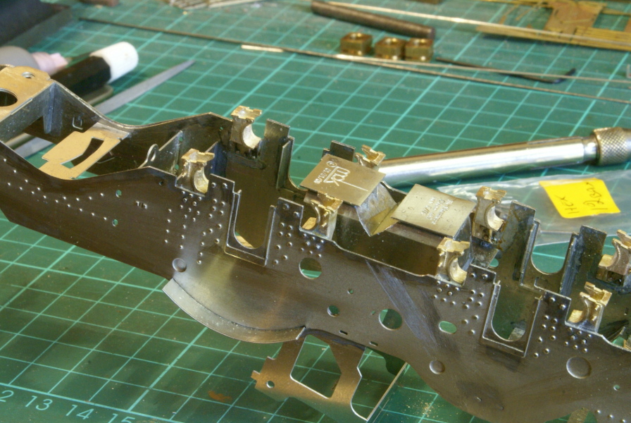
So laying out the frames and 14 frame spacers are layed out. The brackets for the CSB are soldered to the frames. The ashpan is showing the cutout required to clear the spring wire. Most of the spacers will only fit one way so you can’t really go wrong, the only couple that needed care was the large X frame with the etched writing on, I wasn’t sure how much of this would be visible under the boiler so I made sure this faced downwards and the the other one was the bolster attachment frame for the front pony truck. The slot and tabs allows it to mounted either way round, the attachment holes should be towards the rear and this matches up with the side frames. All the spacers are soldered to one frame.

Frame
Once soldered up the majority of tabs all have to filed off, half a dozen need to be left to mount the etched rivet overlays later so I circled these with a marker pen so that I wouldn’t get carried away and file them all off. The vertical frame is part of the motor mounting system.

Frames with overlay

Frames including overlays
Once the tabs were removed the thin etched overlays for the frames were soldered on. They are held in place with a few tabs and then worked around the edge soldering them together. The remaining tabs were then cleaned up and a small splasher is soldered over the rear driving wheel position.

Rolling chassis
Finally to get the satisfaction of having a rolling chassis the driving wheels were fitted for the photo.
Chassis Detailing

Tapping 12BA
With the chassis built attention now turned to some of the detailing. The next bit on the chassis was fitting the driving wheel springs and hangers. The instructions mention a couple of ways of fitting then, one is to solder them all in place, the alternative was tapping the hangers and bolting it together with 12BA bolts. So that I could drop the wheels as a unit I decided on the drilling and tapping route.
So 12 hangers were drilled and tapped 12BA.
Frames
Soldering all the hangers onto the frame was fun(!), the casting was a good heat sink so getting the soldering iron in was entertaining, it might have been easier to do this before putting the frames together but I got it done without buckling the frame overlays.

Brake bar
The bottom block was soldered to the hanger on one side, the spring can be fed into the slot, the block on the other side is then used to clamp the spring in place. This can be seen on the frame in this picture, the hangers on the left have the bottom block soldered to them. This also shows the castings for the brake rod, note this can go 2 ways and it’s not that clear in the instruction – I just hope I’ve got it the right way round.

Spring hangers
So finally the brake lever is fitted and one spring. The bits that need soldering have been done, it’s quite fiddly fitting with all the 12BA bolts and the heads on the bolts are a little too big for my nut spinner which makes it awkward to bolt up and the close up photo emphasises the large head. I think I’ll make up a nut on a threaded bar instead so that I can use the nut spinner and it’ll look the right size then. That’s a job for later after a bit more detailing on the frame.

Springs fitted
So the bolts have been replaced with 12BA nuts soldered to some studding.
Rear Beam and Steps

Rear steps

Rear beam
The rear buffer beam and steps are part of the chassis. There are some triangular re-inforcing webs behind the buffer beam. The ones supplied in the kit are fine for the finescale version but for Scale7 with the wider frames these are too wide. I couldn’t find the replacement Scale7 versions but it was very simple to trim the supplied etchings to fit the Scale7 frames. Otherwise the steps folded up and fitted together without any problems and there is a half etched overlay for the rear buffer beam.

Rear beam
Again this is where reference to prototype photographs are required. On some locos there is a box underneath the rear buffer beam and the relevant parts are supplied in the kit. However for my chosen prototype there is no box fitted so the rear beam was tidied up.


Leave a Reply