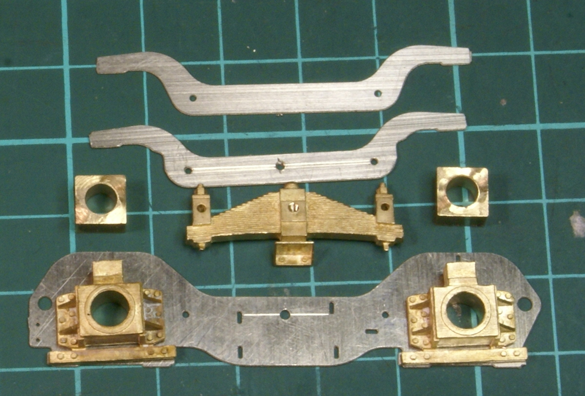
Rear bogie components
The rear bogie again is a mulitude of etchings and castings but it is all clearly covered in the instructions. There are 4 hefty castings for the axleboxes and this may be the only small problem if building the bogie as standard. As with the pony truck the axleboxes castings are designed for a 3/16″ axles but the Scale7 wheels are supplied with a 5/32″ axle so some bushing will be required. The only reservation I had with the rear bogie is, that as standard it builds as a rigid unit. It has a very nice central bolster with side control springing, the attachment to the chassis was also built on a sprung unit.
However having gone to all the trouble of springing the drivers I decided that I had to have the beam compensation working on the bogie. This took a little while mulling over how to modify the bogie but this is the solution I eventually decided on.
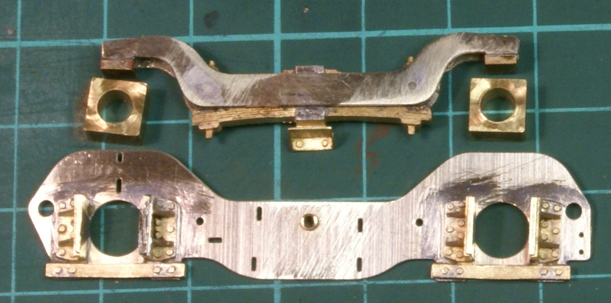
Modified horn blocks
First the axlebox castings are attacked with a hacksaw to remove the axle boxes and leave hornblocks attached to the bottom keeper plate, these are cleaned up to provide a smooth sliding fit for the new axlboxes turned up from a length of 1/4″ square brass bar stock. The brass casting for the spring is then drilled and tapped 12BA to provide a pivot point prior to fitting the etched nickel beam pieces. The main bogie side is also drilled for the pivot point and a small brass bush is turned up in the lathe with a 12BA clearance hole.
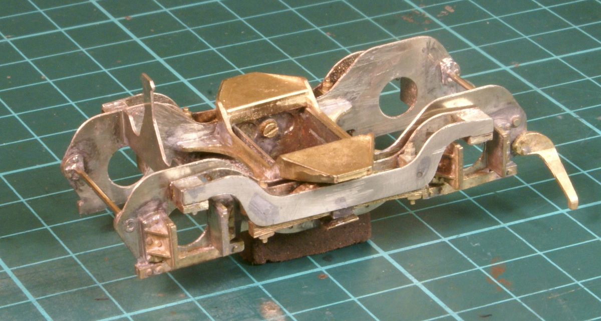
Beam compensation
The top of the axlebox castings were cut off and soldered to the beam to provide a rocking pressure pad on the new axle boxes. The rest of the bogie was constructed as per the instructions.

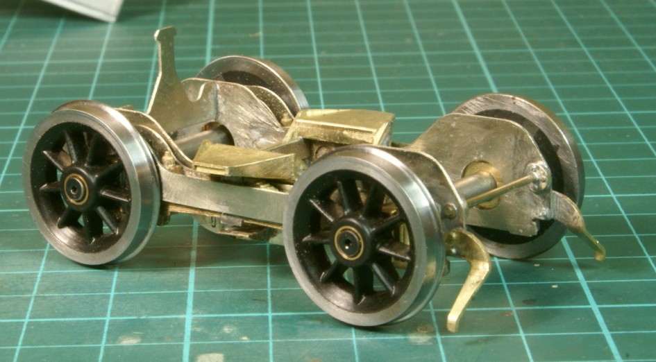
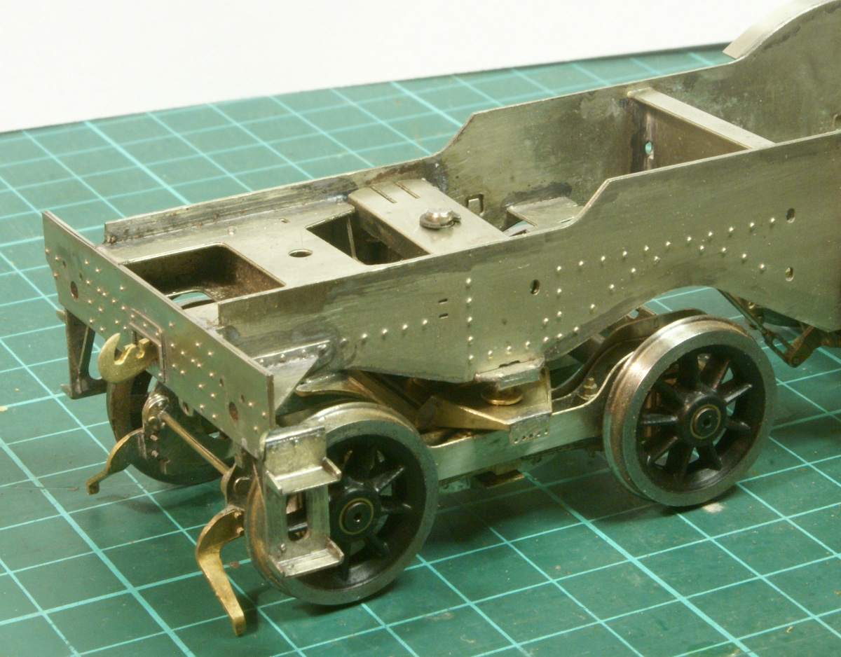
Rear bogie
The upright etching at the front of the bogie slots into the chassis and with a clever locking plate retains the bogie in position when the loco is lifted from the track.
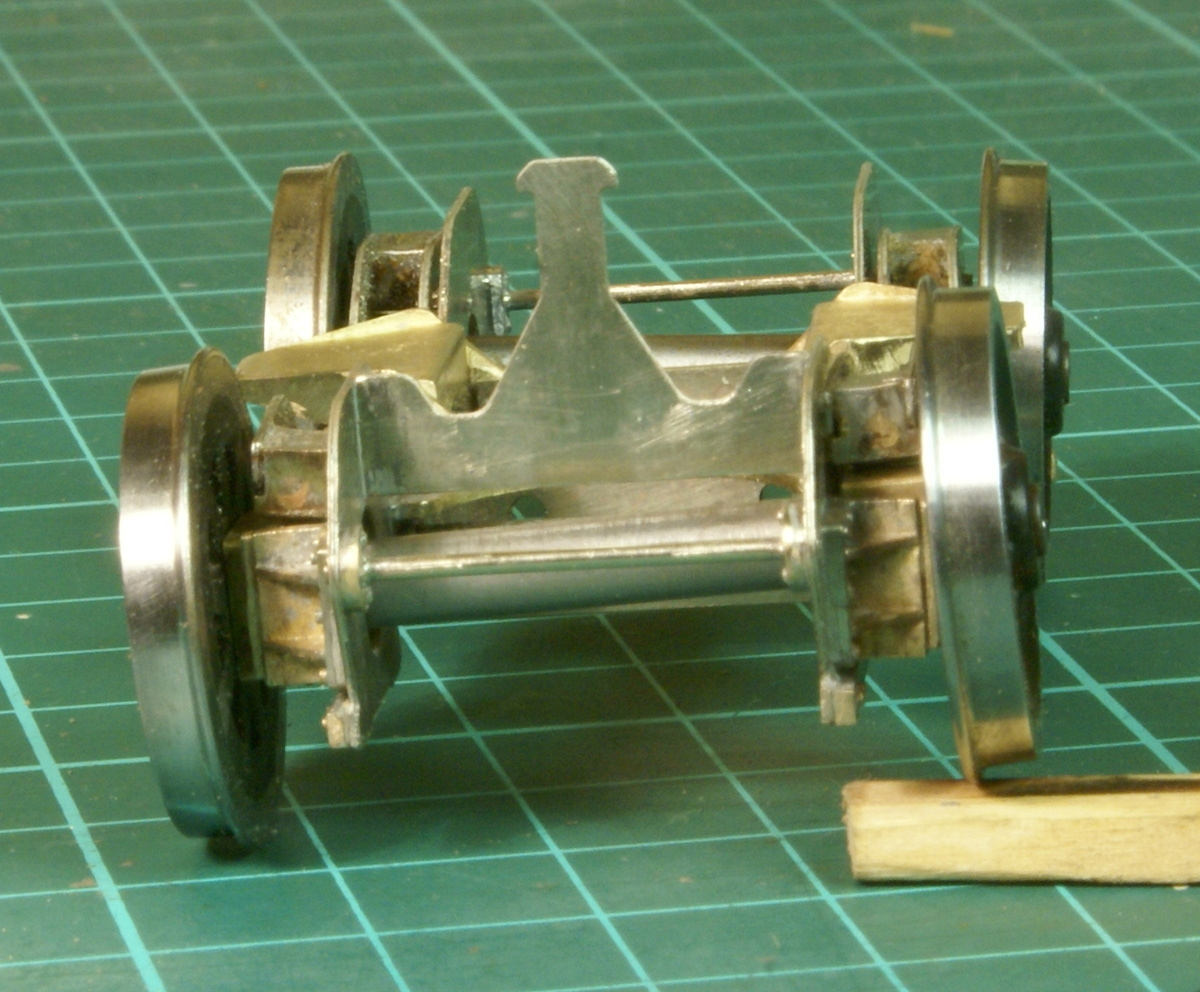
Running over a matchstick
Finally to show the beam compensation in action the bogie is running over the obligatory matchstick!
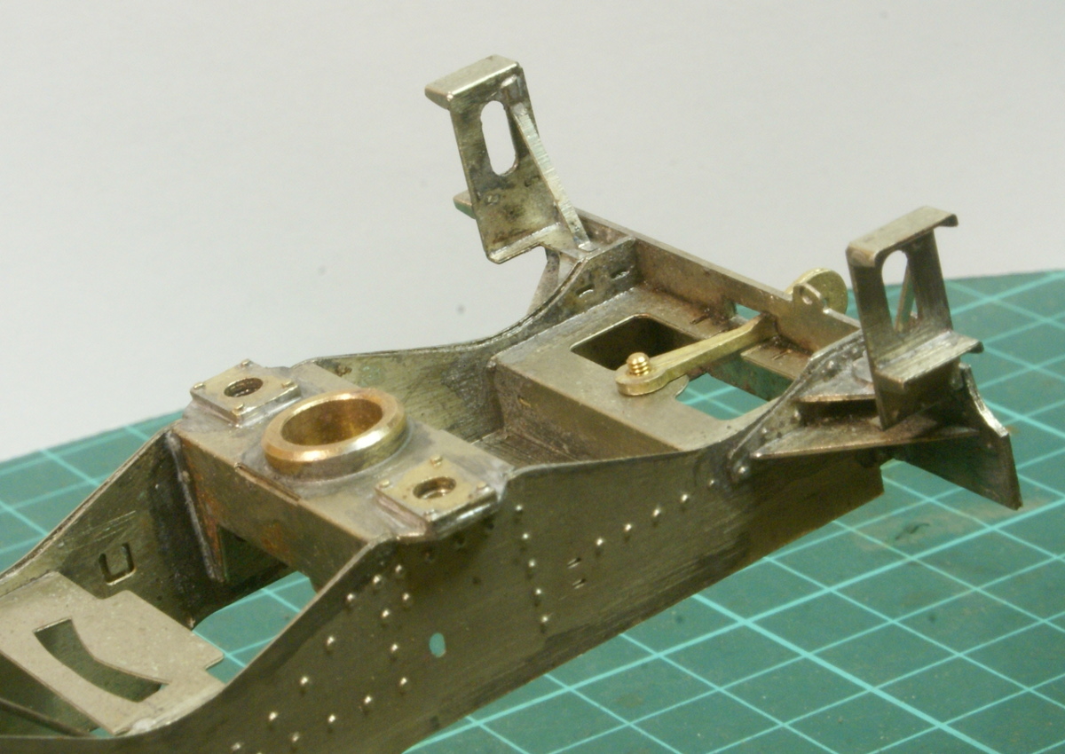
Rear bogie attachment
The bogie attachment to the chassis is also another work of art. On the chassis cross member there are sprung plungers either side to control the lateral rocking.These have bearer plates on the lateral cross member for which a couple of nice brass castings are supplied. These are not going to be seen once everything is fitted but they are there. Also in this photo in the bottom lefthand corner there is a cross member with an arc on one side, remember the upright etching on the bogie, this slots into this cross member.
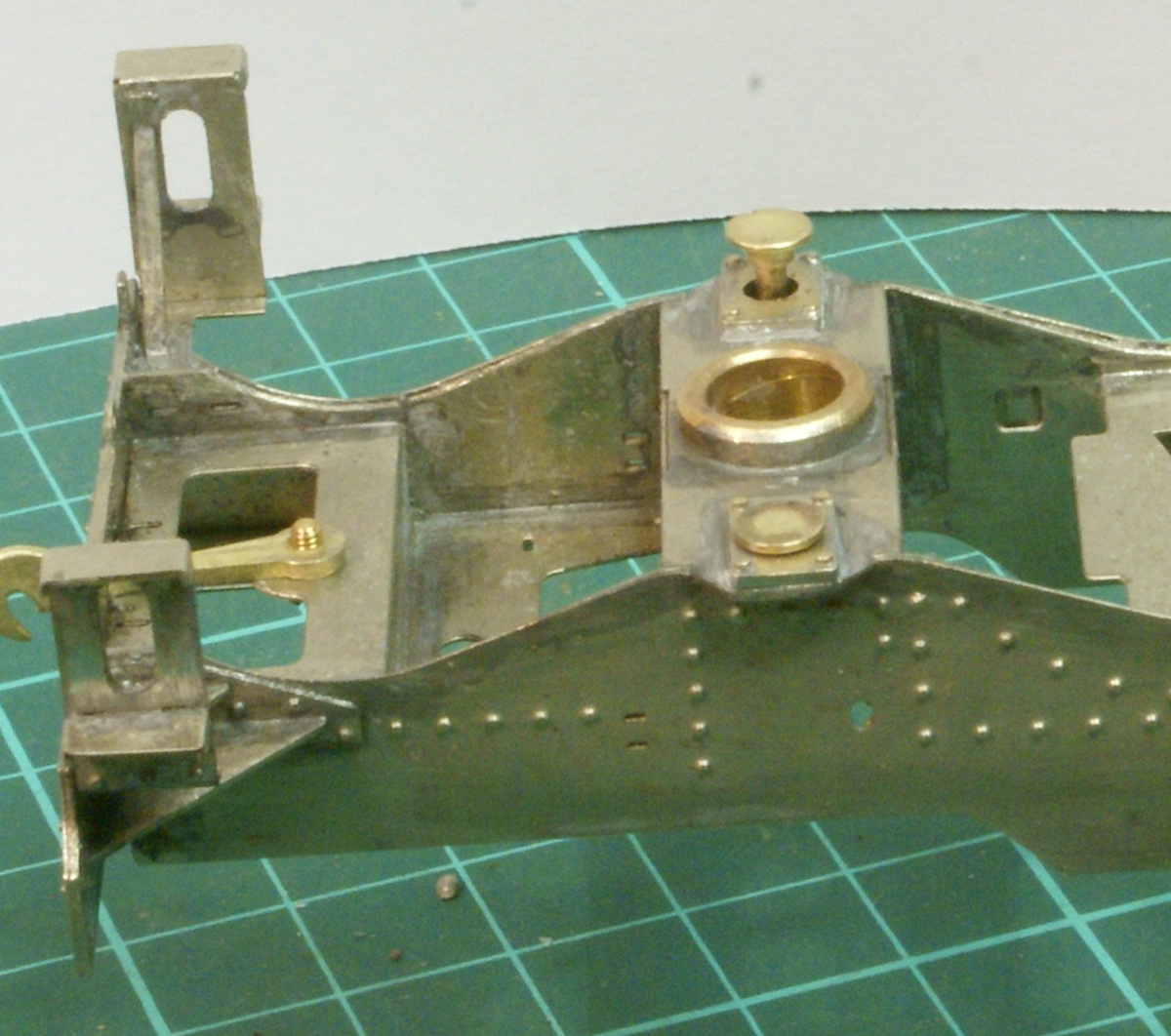
Rear bogie lateral control
As can be seen in this photo the lateral control plungers have been fitted into the chassis prior to fitting the bogie.
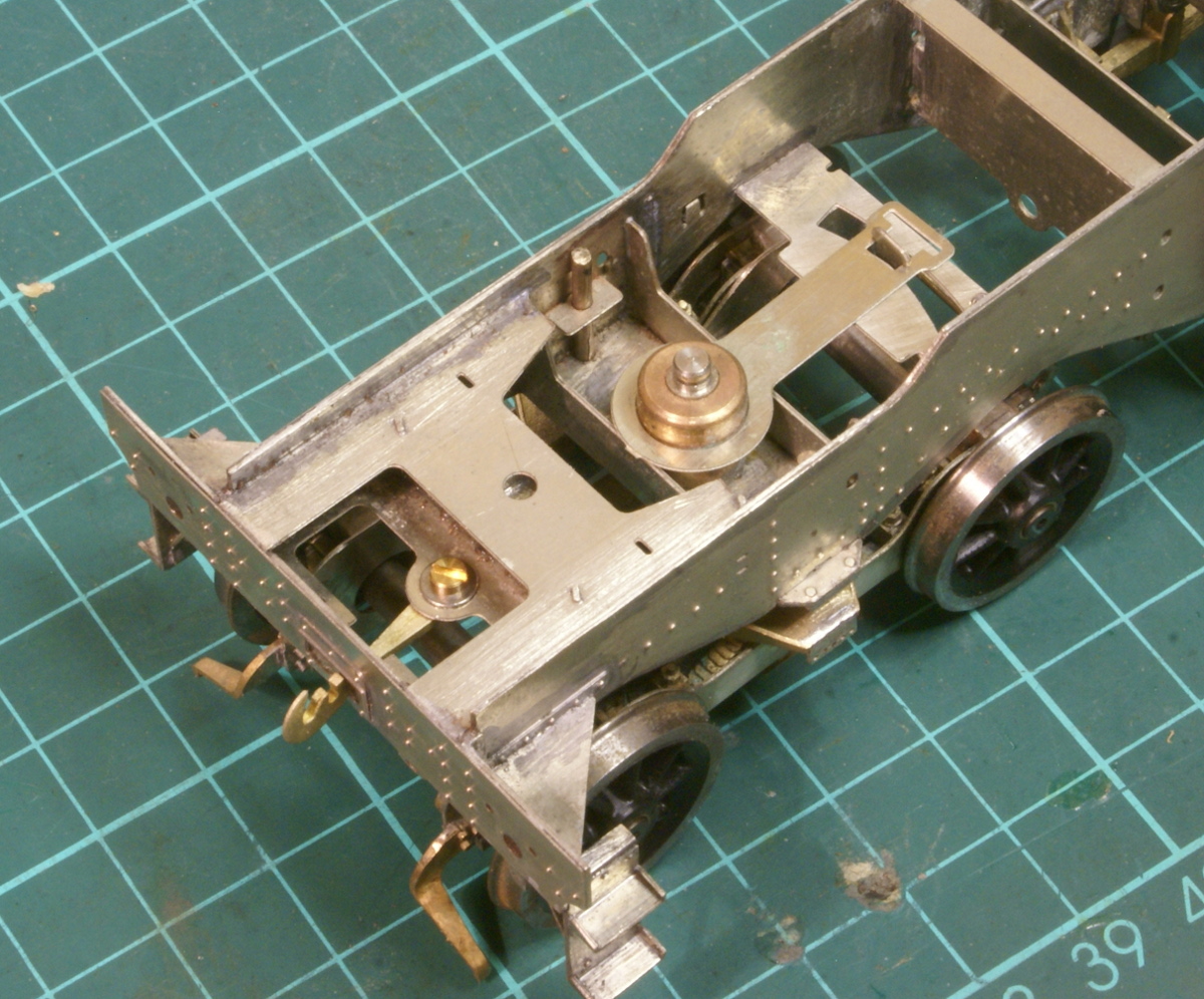
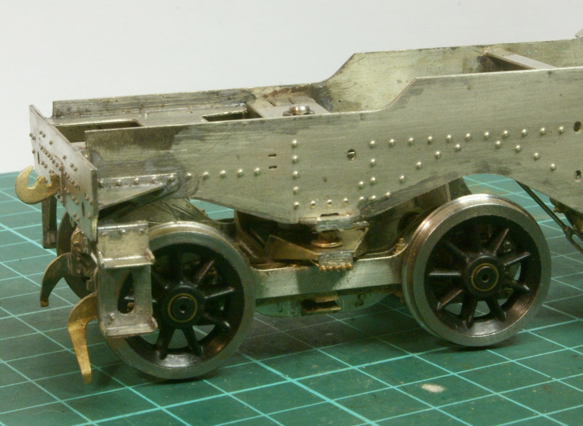
Rear bogie fitted
The fitting of the bogie to the chassis shows the keeper plate fitted over the tang from the bogie. This limits the movement of the bogie if the loco is picked up, it will keep the bogie more or less level and stop it from spinning around. The top of the lateral control plungers can be seen just inside the main chassis etching.
Rear bogie fitted
A cross beam is then fitted which provides a small amount of springing to the lateral control plungers, a small cir-clip holds it all in.
Fitting grease nipples
One final bit of extra detailing – on the bogie cast bolster there are some end plates with 5 etched holes. Looking at the prototype photos this is a plate holding 5 greasing nipples for the bogie. My first thought was just to feed through some copper wire to give an indication of the pipework. However the greasing nipples have a bit more bulk to them compared to the pipework. So instead I fitted some scale hardware bolts to the plate and bent the rear of them to give the impression of the pipework.


Leave a Reply