The kit as supplied will build a rigid 6 coupled chassis, however I prefer to build locos with some form of suspension. Although a rigid chassis seems the simplest option in my opinion it demands the greatest accuracy in the build, you have to get all axles precisely aligned and the chassis square. At least with a sprung chassis it can soak up some of the inaccuracies I introduce.
For this build I decided to try a system called continuous springy beam suspension, as developed by members of the Central London Area Group of the Scalefour Society. This seemed to offer the benefit of the advantages of beam compensation and individual sprung compensation all in one package.
Preparing the frames
Prior to starting on the frames the following items were purchased
- set of S7 wheels from the Scale7 group stores
- cast hornblocks from Fourtrack models – now available via Meteor Models.
- etched steel coupling rods from Slaters.
Steel Coupling Rods
So the first job was to make up the coupling rods as these will be used to align the hornblocks in the frames. I’m not a great fan of nickel rods and gear, it always looks too yellow to me. If you want something to look like steel rods then you have to use steel. Also the etched units supplied in the kit appear to have over sized diameter bosses. Hence I went for the Slaters etched steel gear, these comprise of several layers of etched steel to be laminated together. So I knocked a couple of panel pins into a block of hardwood. These provided a stop against which I could push the various laminates with another smaller block of wood whilst I soldered them together, I used a couple of cocktail sticks on the holes to keep them aligned. Once completed, I turned to the frames.

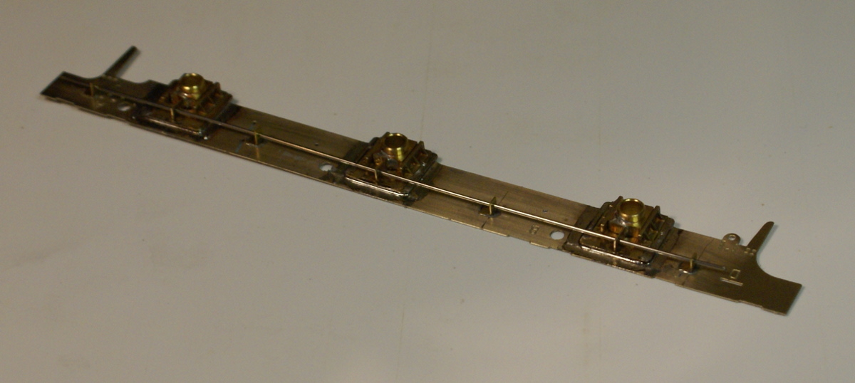
Laying out the frames
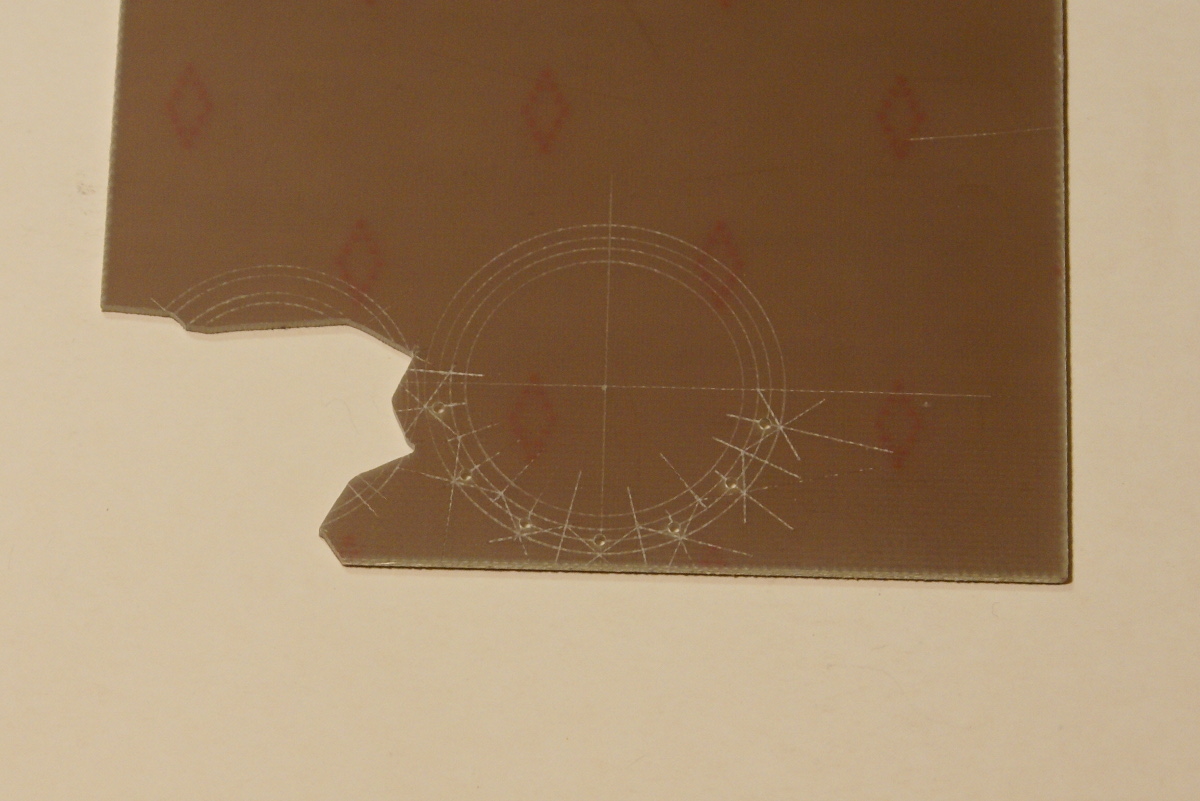
The frames were removed from the etch and sweated together. I have used a little bit of solder at each end to tack together the two frame etches from the kit. I actually used the bearing bushes supplied in the kit through the axle holes to locate the two frames. Once soldered together I then used a square and odd-leg calipers to mark out the cutouts required for the hornblocks. The one on the left has been cutout using a piercing saw. The photo also shows the Slaters coupling rods nearly complete ( more on that in a minute). Also the 3 hornblocks along the bottom have steel pegs in them. These are used to set the hornblock spacings, the finished coupling rods sit on these pegs. I turned these up on my lathe but similar chassis dowels are available from various 7mm suppliers.
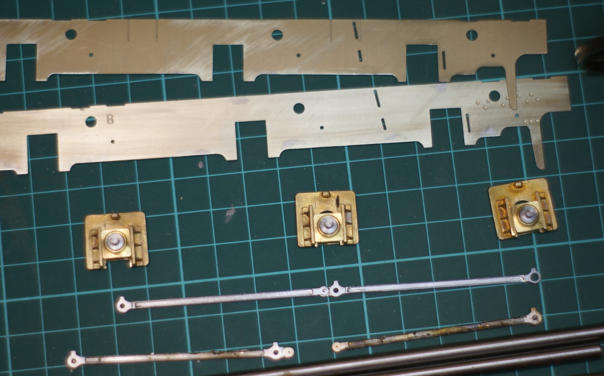
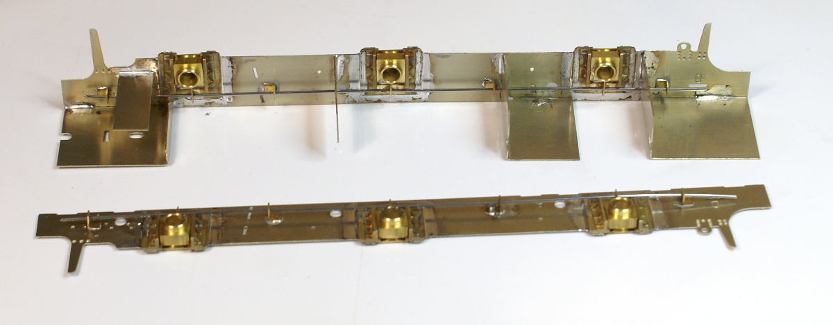
frames
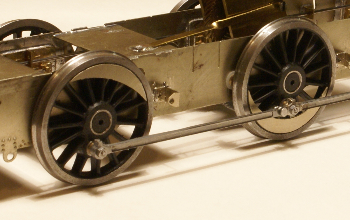
The next photo shows the frame cutouts completed and the 2 frame pieces separated. I’ve included this one to show the coupling rods. The Scale7 crankpins are supplied with a brass bush. On top of the crankpin this adds a bit to the clearance diameter required in the coupling rods. The right-hand boss on the top coupling rod shows how much had to be drilled out! This was a time to be brave as there isn’t a lot of metal left! You have to be confident and quick drilling this out. As these rods are several etchings soldered together if you took it easy then the heat build up from drilling would melt the solder and separate the etchings as I found out.
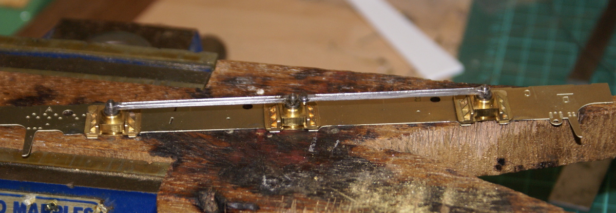
Setting out the horn blocks
The final photo shows the hornblocks ready for soldering to the frames. The coupling rods are finished and located on the steel dowels on the top frame. A nice 75 watt Weller soldering iron was used to sweat these to the frames. Note when soldering anything like this, a thin frame and a glorious heatsink of a hornblock use the iron to heat up the heatsink to get a good joint. If you put the iron on the thin frame then you’ll never get enough heat into the brass casting to get a good joint.
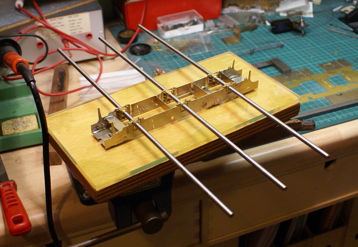
Continuous Spring Beams
Continuous Springy Beams
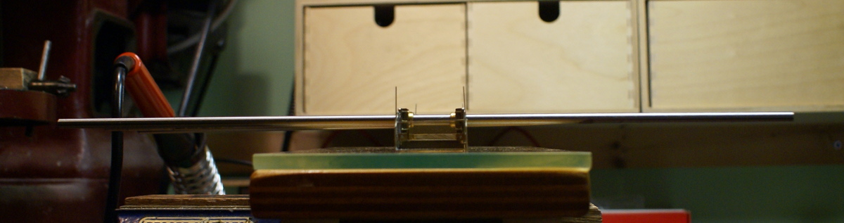
Fortunately the CLAG website has a set of dimensions for the 8’0″-8’6″ wheelbase in setting up the pivot points, these were scaled up for 7mm. So on the top of each hornblock I soldered a small piece of brass angle. I then threaded a length of silver steel through adding in extra brass L-pieces for the pivots. I then set the hornblocks in position for the right ride height and then soldered the pivot points at the positions previously marked. I then replaced the silver steel with the spring wire.
This was surprisingly rapid once I’d decided how to do it. Probably 30 minutes to make the brackets and then an hour of set up and soldering completed the job. It was great to see very quickly a working system, pushing up on an outside hornblock, you could feel the springing and also see the centre hornblock move down slightly in compensation.
With frame spacers
The frame spacers in the kit are far too narrow for S7 so I cut a strip of 18thou nickel sheet 28.5mm wide for the new spacers. Having put the kit together I think I could have managed with 29mm frame spacers. The nickel silver strip was then trimmed to length and folded similar to the kit supplied spacers and then soldered to one frame.
High tech alignment jig
I was then ready to solder the frames together. Here’s my super deluxe chassis alignment jig, three 12″ lengths of silver steel. I’ve never used any of these fancy alignment jigs, too expensive for me, especially when I have a nice cheap solution that works fine for me. So the chassis is placed inverted on a glass plate to keep it square. The silver steel rods are pushed through the hornblocks. Now because of their length they will amplify any error in the hornblock alignment.
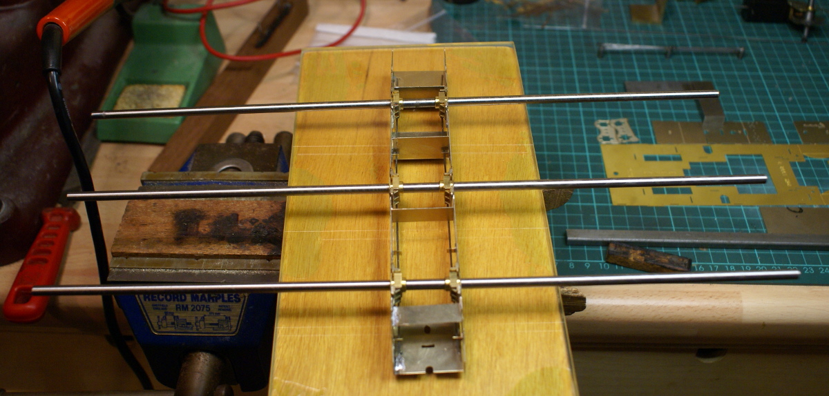
Chassis alignment
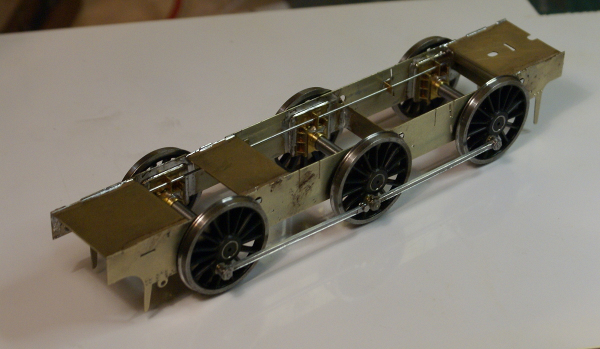
Looking along the length of the chassis all three should lie in the same plane. If one sticks up then it needs adjusting. Similarly in plan view the three rods should be parallel. Once soldered up, I dropped in the wheels and added the coupling rods.
Chassis alignment
On the bench it all ran smoothly but running it down the test track revealed one slight tight spot. The usually trick to find which joint is binding is to waggle each coupling rod. I quickly found the culprit but when waggled the rod freeded itself up which was a little strange. It seems that the brass bush on the crankpin was a bit wider than the thickness of the coupling rods. As long as the rods were tight up against the wheels it was fine but as soon as the rod moved sideways on the crankpin it started to bind. So a little judicious filing to reduce the height of the brass bush stopped any lateral movement on the crankpin and resulted in a nice free running chassis.
rolling chassis
So first impressions of the bendy beams is very encouraging, it was very simple and quick to build the suspension. I have what seems to be a sweet running chassis. Dropping the wheels out of the chassis is like a quick release system, because there are no keeper plates or retaining screws it’s just a case of pulling out the the two wires and the wheels drop out. So I’ve still to finish the kit to test it in operating conditions but I think I’ll be using the system on my next scratchbuild effort.
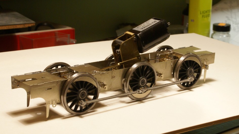
Motor, gearbox and pickups.

with motor
The motor and gearbox is a standard VML2 unit from ABC gears. Originally I mounted this with the motor in the firebox but this was extremely tight on space and was close to the cab spectacle plate. So I then turned it around and it fits quite neatly into the boiler. A small brass torsion strip was soldered to the chassis to stop the motor rocking backwards and forwards yet still allows the suspension travel on the centre axle.
The pickups are carbon plungers which I picked up from a GOG trade show, they might have been from Ron Chaplin. These were design for 7mm finescale so were too thick as the wheels are a lot closer to the frames in S7, the plastic bush was shaved as thin as possible to clear the wheels.
Brake gear and detailing
brake blocks
The supplied brake blocks in the kit are etchings, which I’m not too keen on as it’s a potential source for short circuits. I made replacement ones from paxolin sheet. Various circles are marked out on the sheet, 8BA clearance holes drilled so they can be mounted on the hangers. They are then cut out and mounted on the hangers.
The white metal sandboxes are too wide for S7, with wheels being closer to the frames then if fitted they would foul on the coupling rods. I mounted the castings in a mini lathe and skimmed 1/16″ from the width, which avoids clogging up any files. I then tinned the castings and the frames before sweating the sandboxes to the frames. As I was modelling the batch with the filler on top of the tank I reversed the sides on castings so that the bevel on the top was facing the chassis.
To be completed
The final bits to finish the chassis are the sanding pipes, a little bit of inside motion to fill a bit of the space between the frames and painting. I’ll update with a few more photos as I complete these last few jobs.


Leave a Reply