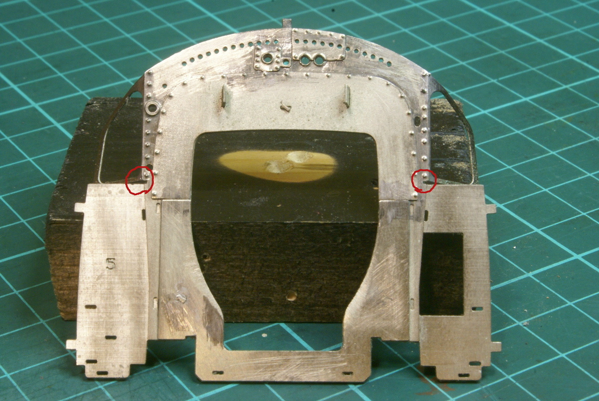
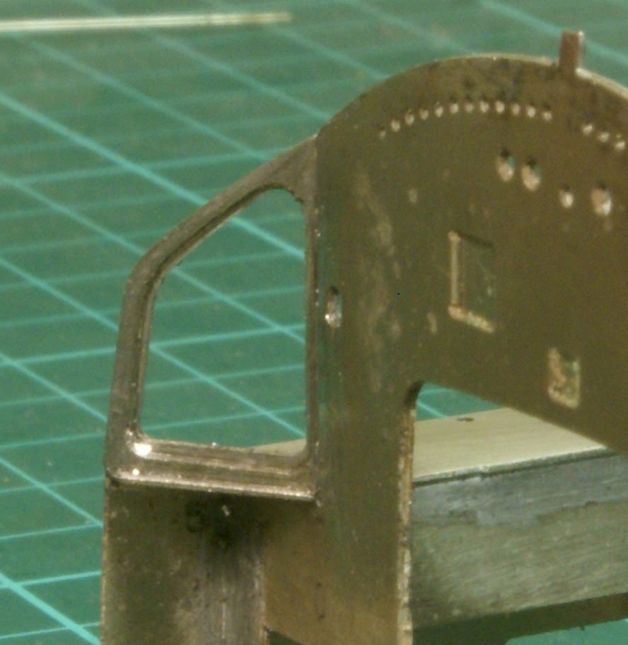
Cab spectacle plate
Now we can get on with building the main tanks for the loco, which starts with the front spectacle plate for the cab. This has another half etched overlay which provides the rivet detail around the top visible part of the firebox. There are then another couple of small etches to fit around the top of the spectacle plate. The window frames need to be folded back by about 60 degrees, again it’s not important as it has a tab to slot into the tank top which provide a positive location. It does need a small slot cut at the base of the windows, this is to allow the tank tops to seat fully. The cutout is circled in the photo and the reason will be seen in later photos.
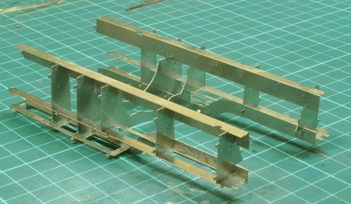
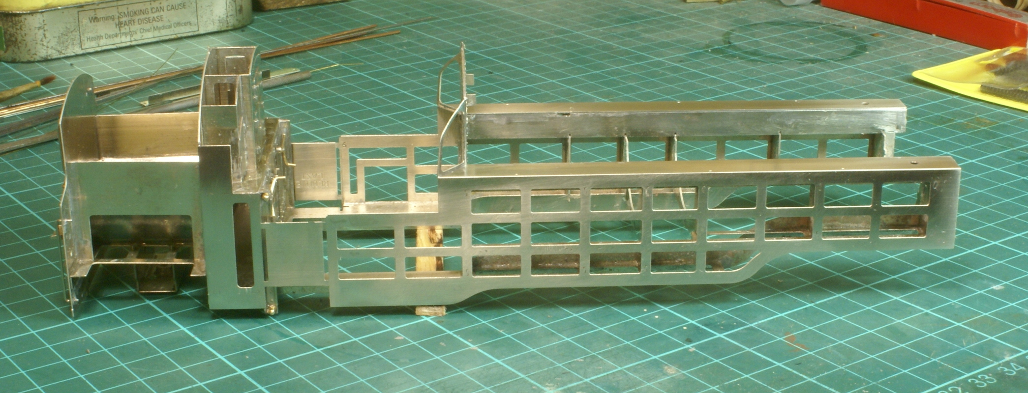
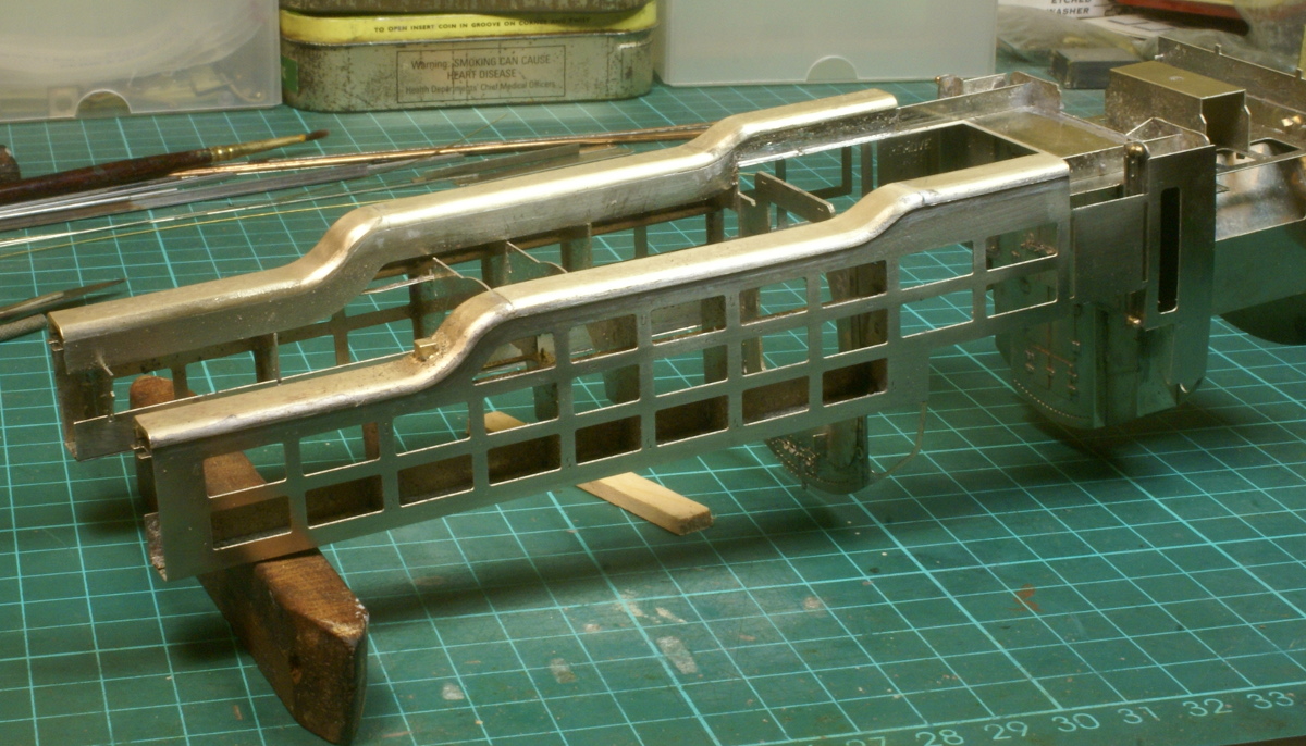
Tank skeleton
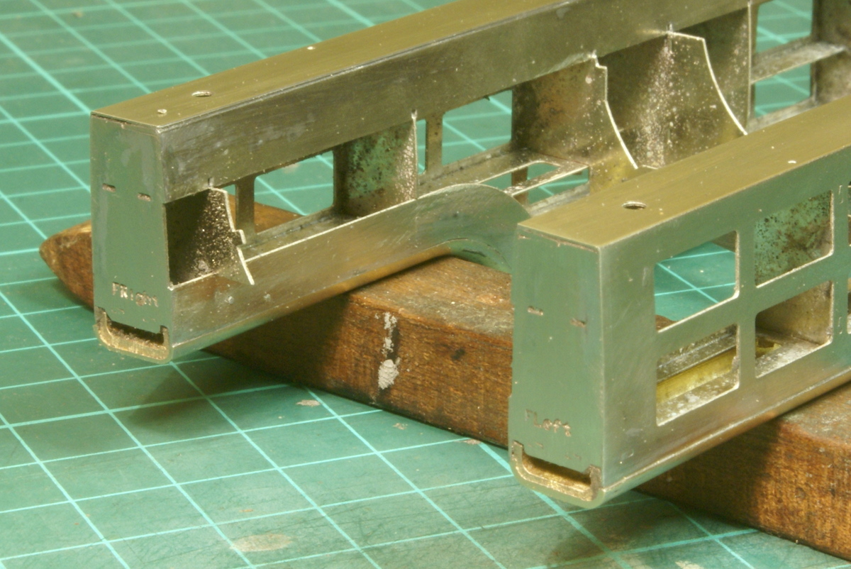
Once that is done then we cut out the multitude of parts which make up the skeleton for the tanks. It’s almost like an aircraft structure with longerons and frames, it’s all fairly simple to slot together and twist the tabs before soldering. A couple of the etches which could fit a couple of ways are clearly marked “outside” so take care but it will fit together neatly.
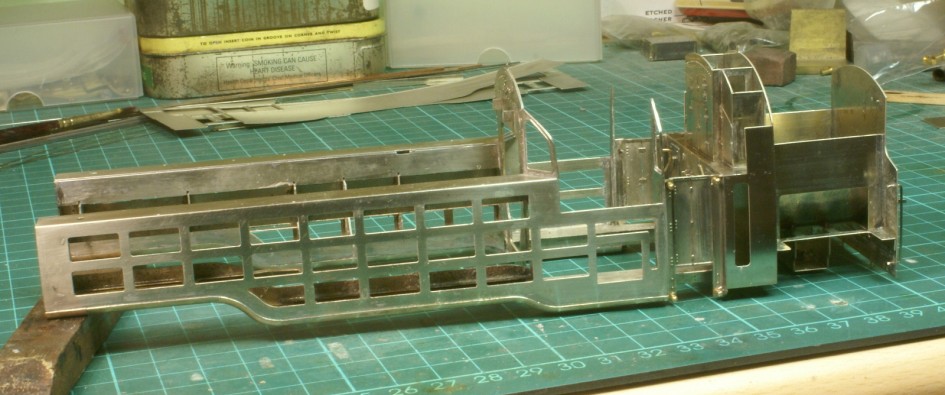
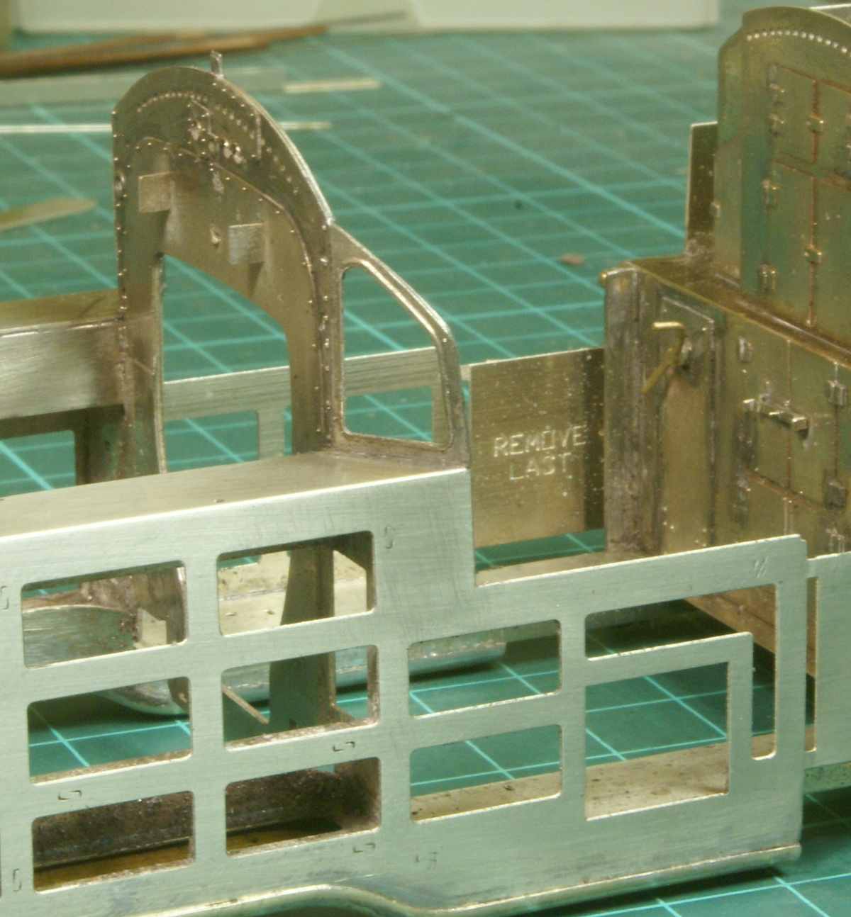
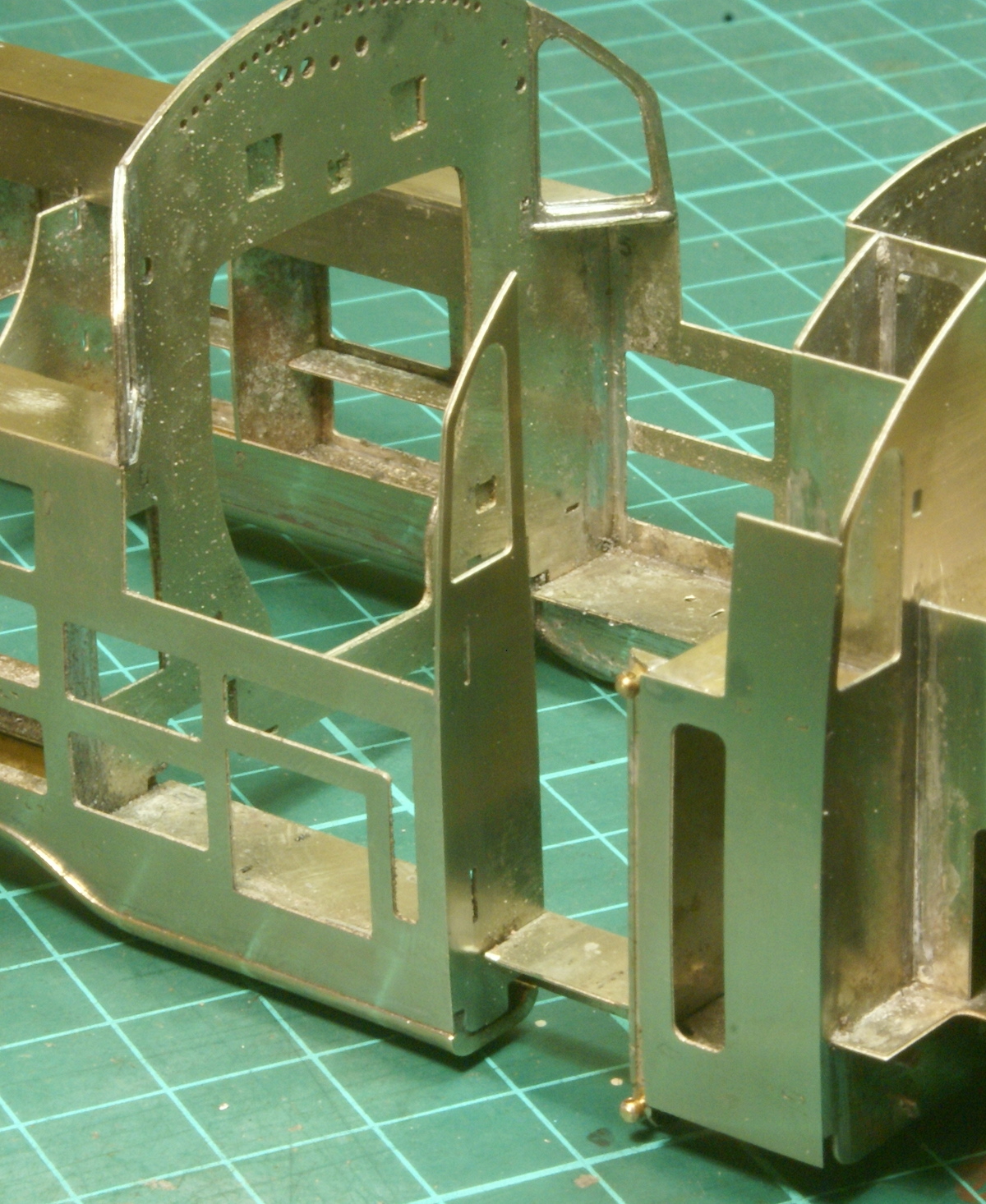
Trial fit of the tank sides and cab
The cab spectacle plate is then attached, tabs twisted but not soldered. The rear bunker is then slotted into place with the cab spectacle plate and tanks and everything is checked for being square. There is a little cab alignment jig with stretches across the top of the cab to ensure that all is held square. As the various components have not yet been soldered up a little gentle twisting of the structure is possible. I used a 12″ steel ruler along the tank tops to see if everything was square and it was, no adjustments were necessary.
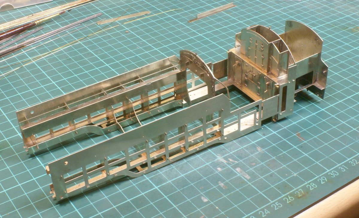
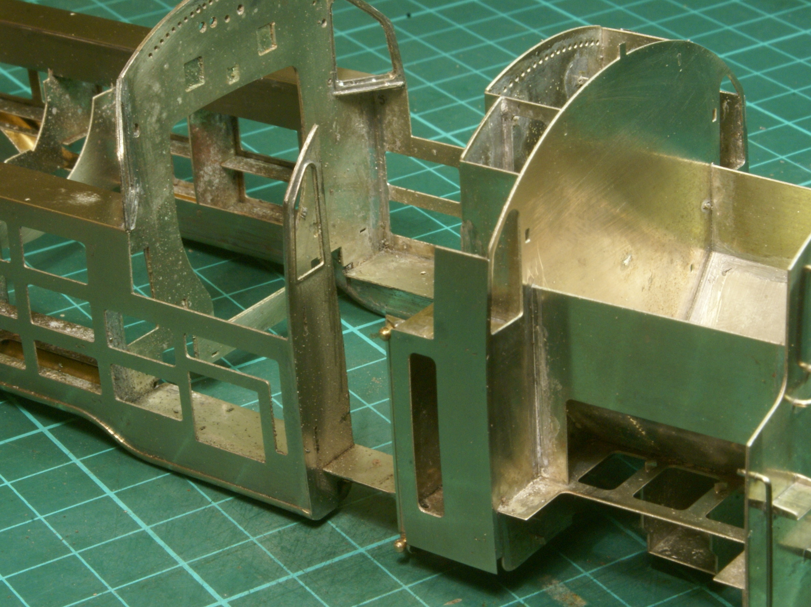
Trial fit of the tank sides and cab
So I soldered the tank framework up and the cab floor but avoided soldering the cab floor to the front spectacle plate as this needed to be separated for a bit more work.
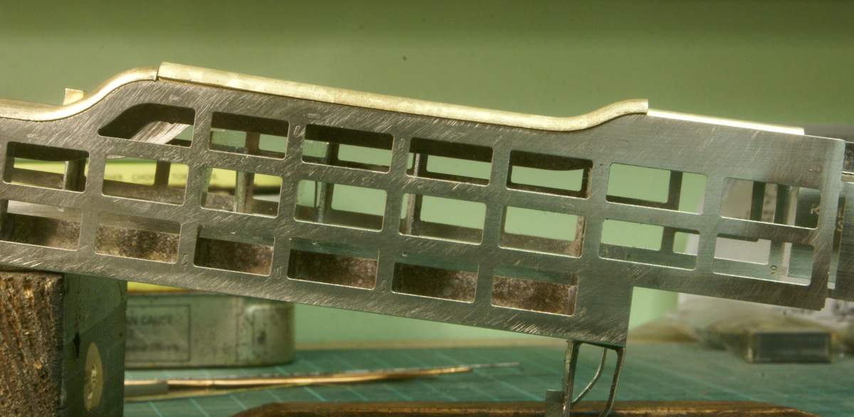
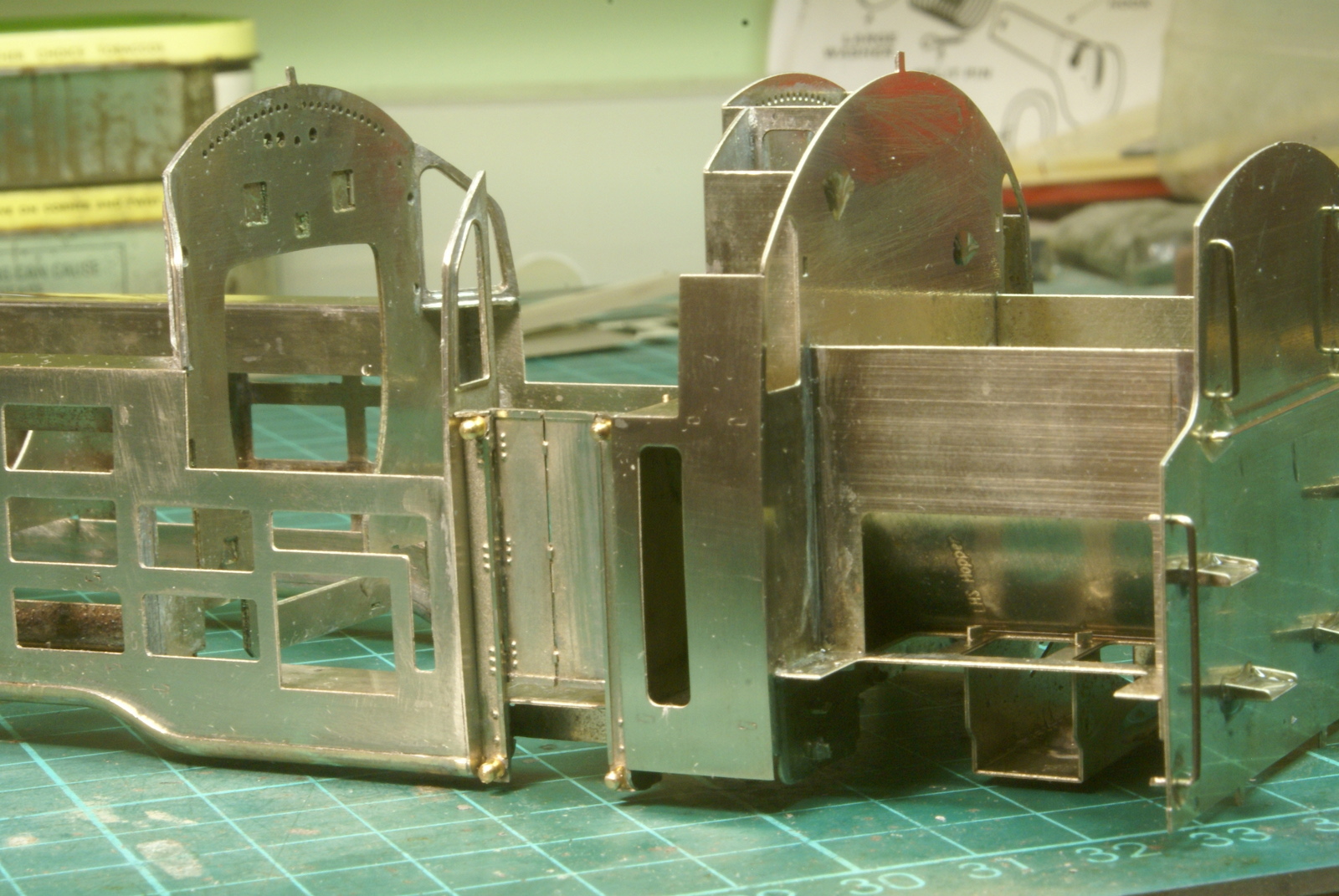
Next the top of outside frame for the tanks were folded to make the tank tops. Now these outside frames are curved to form the shape of the tank so when fitting we start at the bottom and work our way upwards. The tabs at the bottom are twisted and then soldered. We then work up to the next level until we get to the top. In the instructions it recommends using a straight edge pressed against the outside frame when soldering. The final outside overlay is a fairly thin half etched component so any undulations here will probably show up on through the overlay, so it’s impportant to get this part as flat and smooth as possible. The instructions suggest an old file pressed against the outside edge as a straight edge, the only problem I have with this is that the file is an excellent heat sink which makes soldering harder. I have several lengths of hardwood strip, these can be had as decorative strips from any decent timber merchants or diy store. These are great as not only do they provide a good straight edge they are insulators, so it’s a lot easier to solder the joint and holding the wood means that you don’t burn your fingers in the process either! This is where the slot in the front spectacle plate becomes apparent as it allows the top of the tank to fit tightly up against the formers.
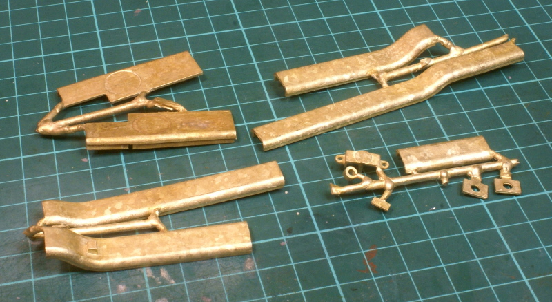
Castings for the bottom of the tank
Once all soldered up it’s a case of trimming all the tabs and getting out a nice large file to smooth everything off. We then turn our attention to the bottom of the tanks. The Standard 4 tanks have a pronounced curve to the bottom of the tanks compared to their predecessors, the Fairburn tanks. On the kit this is modelled by using lost-wax brass castings for the bottom of the tanks. So it was a case of delving into the box of castings for the relevant parts. This was confusing as I knew what I was looking for but could only find five castings. I searched through all the bags before finally consulting the instructions, at which point I found out that there were only five castings required.
Tanks castings trial fitting
On one side it uses three castings but on the other only two are required.These were cut out any offered up to the bottom of the tanks. Now on any long castings do not assume they will remain flat, due to the nature of casting it is unlikely that it will cool uniformly along the length and this can introduce a certain amount of bow. The middle casting being the longest can be the worst offender so check the fitting of the castings. In my case it needed a little tweaking, this was done by putting one end in a vice and gently pulling the other, a straight edge on an engineers square was used to see when it was finally straight.
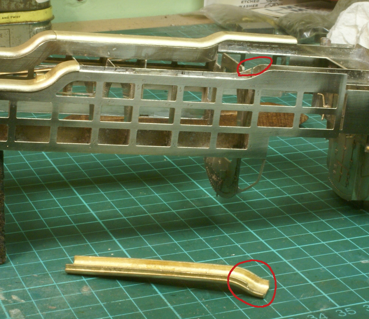
Fettling the tank casting
The castings at the rear around the cab needed a little bit removing, this is circled in the photo. Also the cab floor support frames need rounding off. I think when drawing out the artwork the cab floor supports were positioned slightly too wide apart and so interfere with the castings, still it’s not too difficult to trim them appropriately.
Fitting the castings
So the tanks and the rear bunker were finally fitted together, tabs twisted and then the lower castings were soldered in place. The inside and base of the castings were filed smooth and cleaned up but the outside was left and there is still the half-etched outer tank skin to solder in. The main thing is to thoroughly clean out the step between the castings and the outer skin as this provides the ledge for the outer skin.
Finishing the front of the tank.
The front of the tanks then has an end plate to solder in, yet again more tabs to snip off and file smooth, the entire end is filed smooth in preperation for a half-etched overlay later.
Cab spectacle plate
Cab spectacle plate
The cab windows also has a half-etched overlay to provide the rivet detail and the window frame. This also makes a recess at the rear of the spectacle frame. I strongly suspect that this will be used to locate the glass for the window so extra care is taken to clean this out thoroughly.
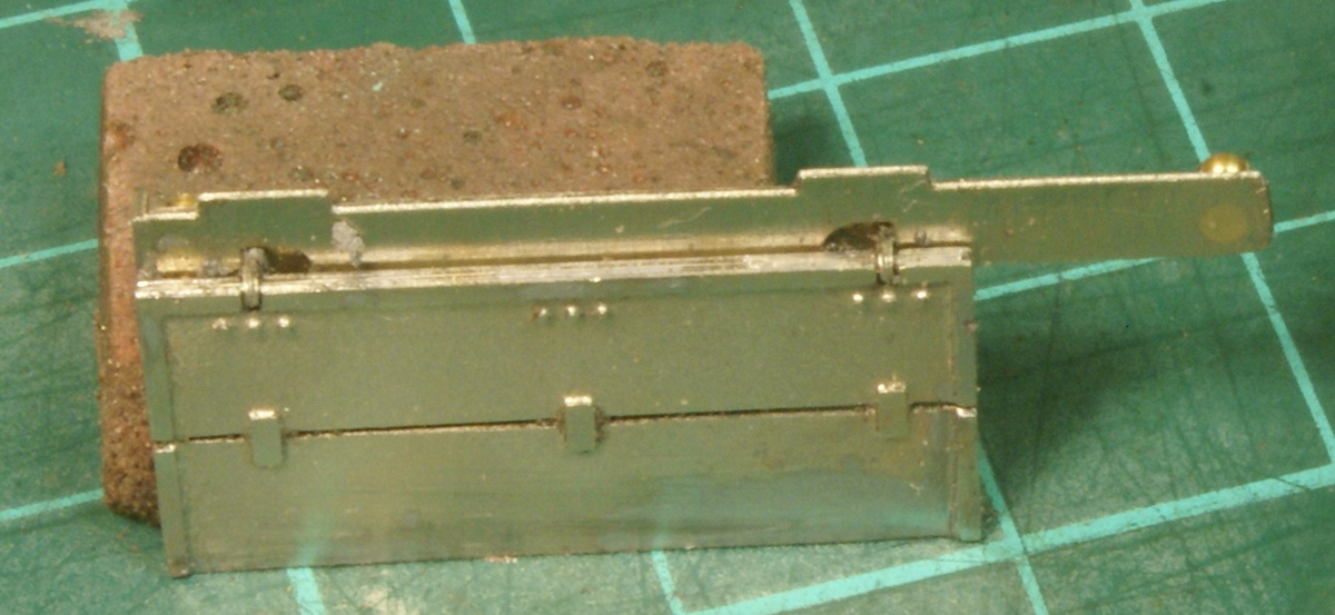
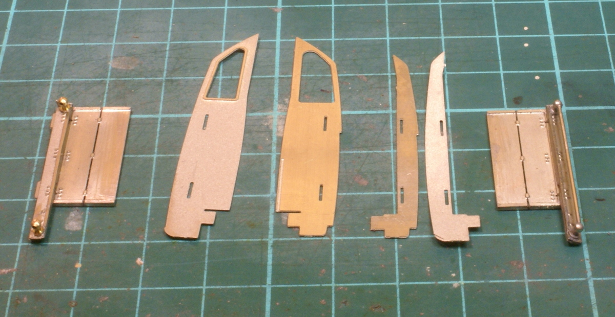
Cab doors
At this point the instructions turn to making the cab handrails and doors. These are again a neat design, the frame has a couple of small tabs that fold out to form the hinges. The doors themselves are two half etched units which along the hinge line have a small half-etched recess. So when the two halves are soldered together there is a slot along the hinge line for a length of 0.5mm wire. This was carefully soldered in place to result in a working door hinge.
Cab doors
The next bit in the intructions starts on soldering on the outer skin of the tanks but it soon became apparent that there was a bit missing. The cab doors constructed are shown in place in the instructions but I couldn’t find this mentioned in the instructions. So the following build steps are not actually covered in the instructions but I think it is important to complete them before fitting the outer skin. Basically at the back of the cab around the door opening there is some extra framework.
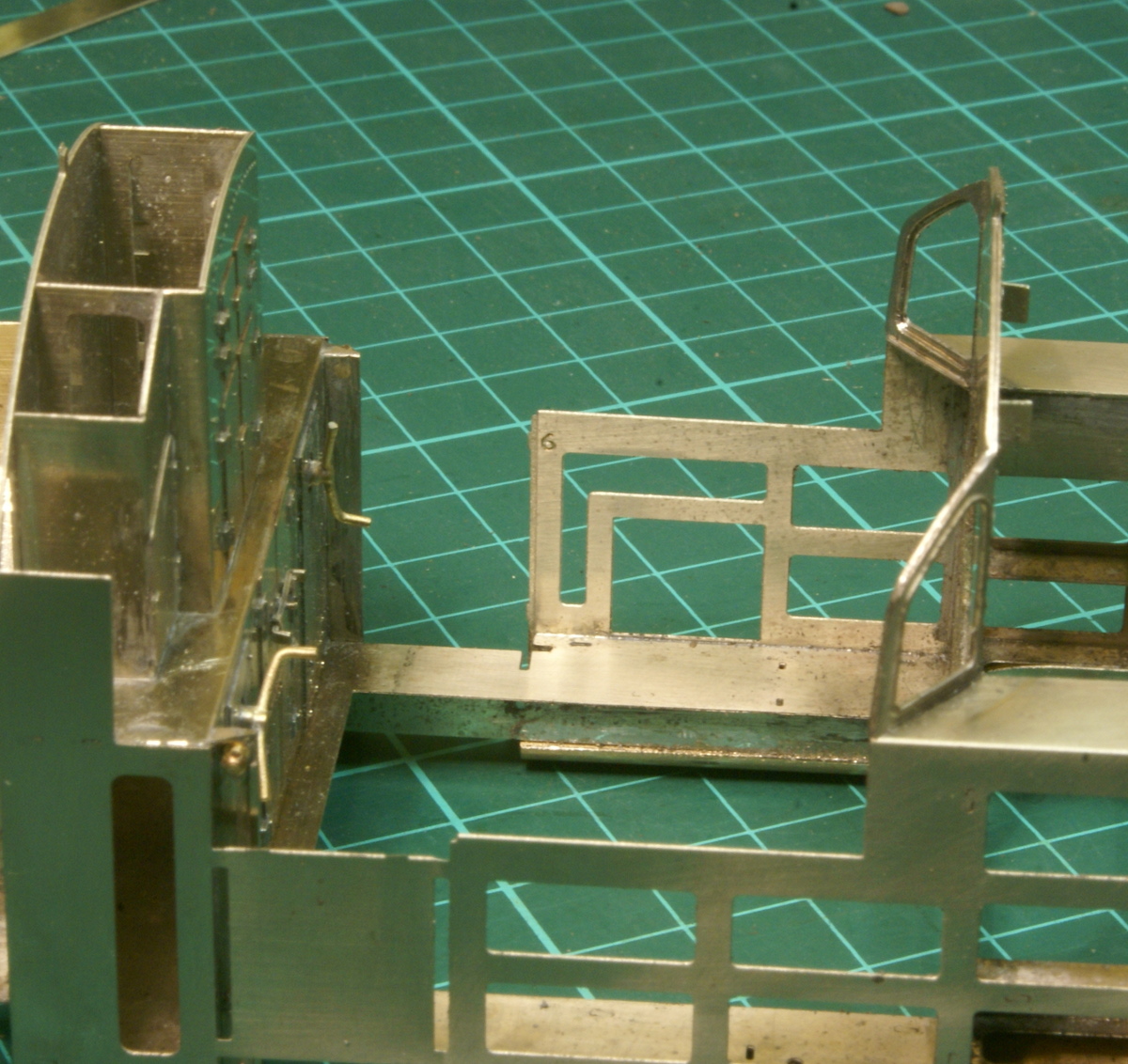
Sorting out the cab doors
This can be seen in the prototype photos in the instruction guide and the components are included on the etches. This comprises of an etched frame with an additional half-etched overlay to provide the rivet detail.However in the current state of build I couldn’t see a way of fitting thes frames as the tank frame had a plate over the doorway, so this was carefully removed. On the inside of the curved tank frame there is a half etched groove around the door frame, this seems to be a locating etch for the side frame so the main pieces are soldered in and the corners are filed smooth and polished.
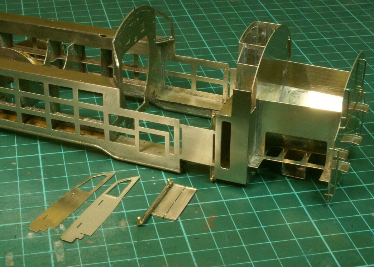
Fitting the cab
The windowed frame is on the drivers (lefthand) side, just a narrow ectching for the right hand side. I then used the door support tabs to locate the half-etched overlay, note this covers the castings at the bottom of the tanks so make sure this is filed flat before fitting.
Fitting the cab
Fitting the etched overlay in the cab doorway.
This is why the slot had to be cut in the cab floor earlier, because when the door support frames are fitted the tabs need space to fit through. So this is the result once the doors are fitted.
Doors fitted
The next stage is to fit the outer skin but as I haven’t done that yet this is where we’ll stop for the moment.


Leave a Reply